LED lighting is often chosen for hot climates because it promises long service life, lower energy use, and stable illumination. Yet the driver can fail long before the LED module itself. Understanding what causes premature led driver failure in hot climates requires more than checking the driver’s rated temperature. Real installations face trapped heat, direct sunlight, dust, humidity, vibration, and inconsistent electrical supply.
A driver mounted inside a sealed sign cabinet may operate several degrees hotter than expected. Metal surfaces can absorb afternoon heat, while poor airflow prevents internal components from cooling. Electrolytic capacitors gradually lose performance when exposed to sustained high temperatures. Loose terminals, undersized wiring, and repeated voltage surges can add further stress. In coastal or dusty areas, contamination may also encourage corrosion and reduce heat transfer around the housing.
This guide examines ten common reasons LED drivers fail early in hot environments. It considers thermal design, installation quality, component ageing, moisture protection, and maintenance practices. The discussion reflects field-service observations and established electrical engineering principles, but every site behaves differently. A driver that performs reliably in one city may struggle inside another enclosure. Ratings can be misunderstood. Measurements may also be incomplete.
Small details matter.
Checking surface temperature, airflow, load percentage, and connection tightness can reveal problems before dark sections appear. Infrared readings are useful, although they require careful interpretation. The following points are intended to support practical diagnosis and better specification decisions. They are not a substitute for manufacturer instructions or qualified inspection. Some failures remain difficult to predict, especially when heat combines with poor power quality. That uncertainty deserves attention.
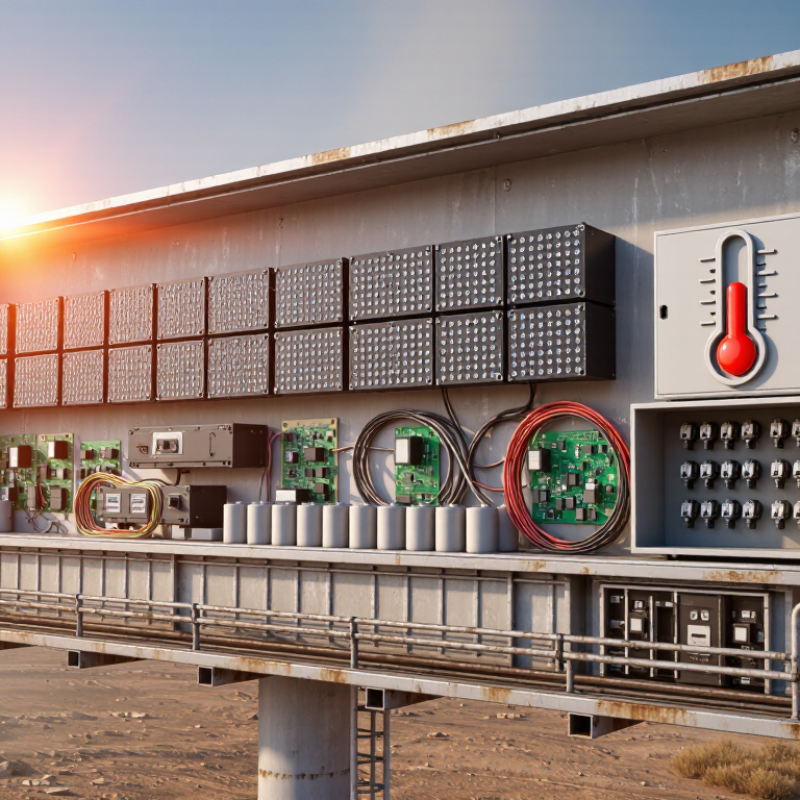
In hot climates, heat does not merely raise LED driver temperature. It accelerates chemical, electrical, and mechanical aging. The ten common causes include high ambient temperature, undersized heat sinks, blocked airflow, sealed enclosures, excessive ripple current, capacitor drying, semiconductor junction stress, solder fatigue, thermal cycling, and poor voltage derating. Small mistakes accumulate.
IEC TR 62380 uses Arrhenius-based reliability models, where many component failure rates increase sharply with temperature. For electrolytic capacitors, the industry’s practical rule is simple: every 10°C reduction can approximately double expected life. A driver rated for 10,000 hours at 105°C may therefore age much faster when installed above a hot ceiling. It is not a perfect prediction. Real installations are messier.
A U.S. Department of Energy solid-state lighting reliability review identifies thermal management as a major factor in long-term LED system performance. Field inspections often find dust-covered vents, dark metal enclosures, and drivers pressed against insulation. These details matter. High ripple current heats capacitors internally, even when the housing feels only warm. Repeated night-day temperature changes also expand solder joints and circuit boards, creating microscopic cracks. Installation teams should measure the driver’s case temperature during the hottest operating period, not during a mild morning. More airflow helps, but better derating is safer. I have seen “cool enough” assumptions fail because the measurement point was wrong.
The chart applies the commonly used electrolytic-capacitor lifetime rule: operating life approximately doubles for every 10°C reduction in temperature. The model assumes a 2,000-hour rated life at 105°C and shows how excessive heat accelerates aging inside an LED driver.
The ten most common heat-related causes of early failure are: electrolytic-capacitor drying, semiconductor junction overheating, thermal-interface degradation, insufficient heat sinking, blocked airflow, high ambient temperature, switching losses, poor solder-joint reliability, surge and transient stress, and enclosure heat accumulation.
Top 10 Reasons LED Drivers Fail Early in Hot Climates
Insufficient Thermal Management and Heat Dissipation
Hot climates expose LED drivers to long periods of elevated ambient temperature. An enclosed driver can become much hotter than the surrounding air. Without a clear heat path, internal components may exceed their rated temperatures.
Electrolytic capacitors are especially vulnerable. Continuous heat dries their electrolyte and reduces their service life. Power switches, transformers, and control circuits also experience electrical stress as temperatures rise. Small errors become expensive.
A driver mounted against a thin metal panel may not transfer enough heat. Poor thermal pads, loose screws, thick paint, and uneven surfaces can create hidden insulation. Dust can block ventilation openings, while sealed enclosures may trap heat. Water protection helps, but it can reduce airflow.
In field inspections, I would check the driver’s case temperature after several hours of operation. Infrared readings can help, but shiny surfaces may give misleading results. A contact probe usually provides better evidence. Measure near capacitors and heat-producing components, not only the enclosure exterior.
Designers should allow thermal headroom instead of operating near the maximum rating. Derating output current can reduce internal losses significantly. Shade, spacing, airflow, and a properly sized heat sink often matter more than expected. I have seen installations fail because the enclosure looked sturdy, yet had no practical heat escape route. That assumption deserves review.
| No. | Failure Reason | Thermal Mechanism | Typical Field Indicators | Indicative Thermal Conditions | Likely Impact | Recommended Control |
|---|---|---|---|---|---|---|
| 1 | Undersized heat sink or metal enclosure | Insufficient surface area and high thermal resistance prevent heat from leaving the driver. Internal component temperatures rise even when the ambient temperature appears acceptable. | Random shutdowns, visible discoloration, shortened service life, or failure after extended operation at full load. | Driver case temperature frequently above 75–85°C; internal hot spots may be substantially higher. | High: accelerated aging and thermal shutdown | Use a larger heat sink, thermally conductive enclosure, or lower-resistance mounting path. Verify the complete assembly, not only the driver module. |
| 2 | Restricted airflow inside the luminaire | Small sealed cavities, blocked vents, dust, and dense mechanical layouts reduce natural convection and trap heat around the driver. | Failure occurs mainly in enclosed fixtures or during still, hot weather; the enclosure remains warm long after switch-off. | Ambient conditions of 40–55°C combined with weak or stagnant airflow. | High: persistent thermal overload | Provide correctly positioned vents where the ingress rating allows, separate heat sources, and maintain clear air paths around the driver. |
| 3 | Operating the driver at maximum load without thermal derating | Power loss increases with output current. Running continuously at the rated limit leaves little thermal margin for high ambient temperatures. | Stable operation in mild weather but intermittent dimming, protection trips, or failure during the hottest part of the day. | Continuous full-load operation at ambient temperatures above approximately 40°C. | High: reduced reliability margin | Apply the manufacturer’s ambient-current derating curve and operate below the maximum output rating when the enclosure is hot. |
| 4 | Poor PCB copper area and inadequate thermal vias | Heat from switching devices, rectifiers, and magnetic components cannot spread effectively through the printed circuit board. | Localized PCB browning, cracked solder joints, hot components near the switching stage, or repeated failures at the same location. | Component case temperatures may exceed the board temperature by 20°C or more in poorly spread layouts. | High: localized hot-spot damage | Increase copper area, use properly designed thermal vias, improve layer-to-layer heat spreading, and keep heat-sensitive components away from hot devices. |
| 5 | Electrolytic capacitor overheating | High temperature accelerates electrolyte evaporation and increases internal degradation. As capacitance and ripple-current performance decline, power conversion becomes unstable. | Bulging or leaking capacitors, increased ripple, audible noise, flicker, delayed start, or reduced hold-up time. | Each sustained 10°C increase can approximately halve the expected life of many aluminum electrolytic capacitors, subject to the capacitor design. | High: common end-of-life mechanism | Use higher-temperature, long-life capacitors with adequate ripple-current rating; position them away from heat sources and reduce internal temperature. |
| 6 | Low conversion efficiency and excessive switching loss | Every watt lost inside the driver becomes heat. Small efficiency differences can create significant temperature increases in high-power fixtures. | Driver housing is unusually hot, efficiency falls at high load, and thermal protection activates during peak operation. | For a 100 W output, 90% efficiency dissipates about 11 W; 85% efficiency dissipates about 18 W. | High: heat rises rapidly with power | Select an efficient operating point, optimize switching components and magnetics, and confirm efficiency across voltage, load, and temperature ranges. |
| 7 | Degraded thermal interface or poor mechanical contact | Gaps, uneven pressure, dried thermal compound, insulating labels, or corrosion increase contact resistance between hot components and the heat-spreading structure. | Large temperature difference between the component and nearby metalwork; failure may appear after months of vibration or thermal cycling. | Interface resistance can add several degrees Celsius per watt, depending on the materials and contact quality. | Medium to high: progressive temperature increase | Use an appropriate thermal pad or compound, control mounting pressure, maintain flat contact surfaces, and inspect interfaces during service. |
| 8 | Solar heat gain and external radiant heating | Direct sunlight can raise the driver and enclosure temperature well above the measured outdoor air temperature, especially in dark or sealed housings. | Failures occur in sun-exposed installations but not in shaded or indoor installations using the same electrical load. | Enclosure surface temperatures can exceed ambient air temperature by more than 20°C under strong sunlight, depending on color and ventilation. | High: hidden ambient-temperature increase | Use shading, reflective surfaces, ventilated housings, thermal barriers, or a mounting orientation that minimizes direct solar exposure. |
| 9 | High-altitude installation without airflow compensation | Lower air density at altitude reduces natural-convection and fan-cooling performance. The same heat load can therefore produce a higher component temperature. | Thermal problems appear at elevated sites even when the measured ambient temperature is moderate. | Cooling performance declines as air density decreases; the required correction depends on altitude, enclosure design, and cooling method. | Medium to high: insufficient cooling capacity | Apply altitude derating, increase heat-sink area, improve airflow, and validate the design at the actual installation elevation. |
| 10 | Thermal cycling and repeated hot-spot expansion | Daily temperature swings repeatedly expand and contract solder joints, component leads, adhesives, and interfaces, causing fatigue and intermittent electrical connections. | Intermittent flicker, startup failure after cooling, cracked solder joints, or faults that disappear temporarily after the unit is moved or cooled. | Repeated cycling between cool nights and hot operating temperatures; severity increases with large temperature swings and rigid interfaces. | Medium to high: intermittent or delayed failure | Reduce temperature swing, improve strain relief, use compliant materials where appropriate, strengthen solder-joint design, and avoid concentrated hot spots. |
In hot climates, LED drivers often fail early when voltage surges repeatedly strike the input stage. Nearby motors, loose neutrals, or utility switching can create sharp transients. The driver may still light, but its capacitors and switching components absorb hidden damage. I have found browned terminals, swollen capacitors, and cracked surge suppressors during field inspections. Heat makes this worse by raising internal temperature and reducing component life. Small events become expensive.
Unstable power is less dramatic but equally destructive. Repeated undervoltage forces the driver to draw more current to maintain output. Overvoltage increases stress across rectifiers, MOSFETs, and insulation. Flicker is a warning, not a cosmetic issue. Measure the supply with a true-RMS meter and, when possible, capture transients with a power-quality recorder. Check neutral connections, grounding, cable length, and shared loads. A surge protective device can help, but it cannot correct poor wiring or sustained overvoltage. Protection must match the system voltage and expected exposure.
During maintenance, leave airflow around the driver and inspect terminals for heat discoloration. Select drivers with documented surge ratings, thermal limits, and protection behavior. Do not trust a label alone. Installation quality matters more than many teams admit. I once blamed heat for a failure that traced back to an intermittent neutral. That mistake changed my inspection routine. Still, measurements can miss short events, and no protection scheme is perfect. Record failures, compare them with weather and load changes, then revise the design.
Hot climates punish LED drivers through heat, moisture, dust, and corrosion. During field inspections, I have found condensation inside enclosures after cool nights. The driver may still start, but its insulation weakens slowly. Humid air enters through loose glands, cracked seals, or pressure changes. Then dust sticks to damp circuit boards. This mixture creates leakage paths and blocks heat from escaping. It is a quiet failure.
Salt air makes the problem harsher near coastlines. Corrosion can attack terminals, solder joints, and protective coatings. High temperatures accelerate chemical reactions and increase component stress. A dusty enclosure may look harmless from outside. Inside, however, airflow can be restricted around heat-producing parts. Repeated thermal expansion also opens tiny gaps. I once underestimated a clean-looking cabinet because I checked it on a dry afternoon. That inspection was incomplete.
Tips:
Use sealed enclosures with suitable ingress protection for the actual site. Install cable glands carefully, and avoid downward-facing openings where water can collect. Inspect filters, vents, terminals, and drain paths during the hottest and most humid months. Look for white residue, green corrosion, swollen parts, or darkened connectors. Keep drivers away from direct sun when possible. Measure internal temperature, not only outdoor temperature. Desiccant can help, but it cannot repair poor sealing. Maintenance records should include dust levels, humidity, cleaning dates, and visible damage.
LED drivers often fail early in hot climates because installation mistakes amplify thermal stress. The U.S. Department of Energy’s Solid-State Lighting reliability guidance notes that driver life can limit complete luminaire life, even when LED packages are rated near 50,000 hours. A sealed fixture installed above a dark roof may trap heat, while undersized wiring creates voltage drops and extra current. Poor grounding and loose terminals add vibration, arcing, and moisture risks. These details look minor during commissioning. They are not.
Component quality matters just as much. Low-grade capacitors can dry out faster near hot heat sinks, especially during continuous night operation. Select drivers with verified temperature ratings, surge protection, and documented test results. IEC and NEMA performance practices are useful references, but certificates alone cannot replace application review. DOE reliability reports also emphasize thermal management and power electronics as continuing reliability priorities. One uncomfortable point: many failures blamed on “bad LEDs” actually begin inside the driver.
Tips: Keep airflow clear around the housing. Measure case temperature after several hours. Tighten terminals to specified torque. Use surge protection where exposure is high. Record failures by date, location, and operating temperature. That simple log may reveal a pattern before a replacement campaign becomes expensive. Maintenance schedules are often too optimistic. Review them after the first hot season.
Heat speeds chemical, electrical, and mechanical aging inside the driver. Small stresses accumulate over time.
Continuous heat dries their electrolyte and shortens service life. A capacitor may fail while the housing feels only warm.
It can approximately double expected life under practical industry rules. This is not a perfect field prediction.
Yes. Sealed or dark enclosures can trap heat, especially above ceilings or under direct sunlight.
Dust-covered vents, insulation contact, thick paint, loose screws, and uneven thermal surfaces can restrict heat transfer.
No. Sealing can protect against moisture but may reduce airflow and trap internal heat.
Measure after several operating hours during the hottest period. Check near capacitors and power-producing components.
No. Shiny surfaces can mislead infrared readings. A contact probe often provides better evidence.
Lower output current reduces internal losses and operating temperature. More thermal headroom is safer than maximum operation.
Temperature cycling expands and contracts circuit boards and solder joints. Microscopic cracks may develop gradually.
Not always. Better spacing, shade, heat sinks, and current derating may be more effective.
A sturdy-looking enclosure is not necessarily thermally suitable. It still needs a practical path for heat to escape.
LED drivers often fail early in hot climates because high temperatures accelerate the aging of capacitors, semiconductors, insulation, and other internal components. When heat cannot escape due to poor ventilation, undersized heat sinks, blocked airflow, or incorrect mounting, the driver operates beyond its ideal temperature range. This increases electrical stress, reduces efficiency, and may lead to overheating, shutdowns, or permanent failure. Understanding what causes premature led driver failure in hot climates requires attention to both thermal and electrical conditions.
Voltage surges, unstable power, weak connections, moisture, dust, and corrosion can further shorten service life. Humidity and condensation may damage circuit boards, while dust buildup traps heat and encourages corrosion. Installation mistakes, low-quality components, excessive loading, and insufficient preventive maintenance also increase risk. To improve reliability, use suitable thermal management, verify electrical protection, seal equipment against environmental exposure, install components correctly, and perform regular inspections, cleaning, and testing. These practices help maintain stable operation and extend LED driver performance in demanding environments.

Lukas Lighting